
Applications such as Voice over IP (VoIP), Financial Trading Platforms, Telemedicine, Industrial Automation, Public Safety Systems, and IoT are highly sensitive to data loss, especially during network disruptions caused by network connection failure. Network routers typically require hundreds of milliseconds to recover from such failures. As illustrated in Figure 1, without protection, when a local link fails (at time t0), the router must first notify its neighboring routers via IGP (at time t1), then recalculate new data paths (at time t2), and finally begin forwarding data over these new paths (at time t3). This recovery process, which can span hundreds of milliseconds, results in the loss of any data sent to the affected destinations during this period.
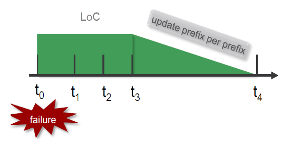
Events: -
t0-t1 - Detect the link failure Using BFD.
t1-t2 - IGP signals the event to all its neighbors.
t2-t3 - recompute new primary next-hops for all affected prefixes.
t3-t4 - pushing the newly calculated route to the RIB/FIB (per-prefix basis).
t4 - traffic starts flowing on the newly calculated shortest path.
Figure 1 Network Failure and traffic handling in the network without protection.
The legacy Fast Reroute (FRR) solution requires additional time to update every destination in the routing table due to the flat structure of the Forwarding Information Base (FIB), as illustrated in Figure 1, between time t3 and t4.
Fast Reroute (FRR) is a critical technology used to ensure rapid recovery from network link or router failures, especially for delay-sensitive and critical services. AS mentioned in Figure 2 ,when a link or router fails (at time t0), the network switches traffic to a pre-configured backup path (at time tR), while in the background, the routing information is updated. This update involves processes such as IGP failure propagation, Shortest Path First (SPF) calculation, and FIB updates. Once the new primary path is calculated, traffic is rerouted accordingly. Without protection, the failure impacts traffic until time t4, but with protection, traffic is only briefly disrupted between the time of failure and its detection, ensuring minimal data loss.
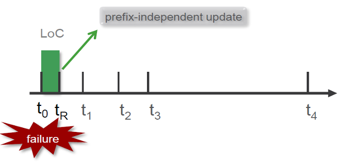
Events: -
t0-t1 - Detected the link failure ( using BFD).
t1 - Traffic move over the backup path.
t1-t2 - IGP signals the event to all its neighbors.
t2-t3 - recompute new primary next-hops for all affected prefixes.
t3-t4 - pushing the newly calculated route to the FIB (per-prefix basis).
t4 - Traffic shifts from the backup path to the newly calculated shortest path.
Figure 2 Network Failure and traffic handling in the network with protection.
Latest Fast Reroute (FRR) solutions leverage a hierarchical Forwarding Information Base (FIB) structure, enabling quick updates to FIB entries by resolving them through multiple levels. This architecture enhances the speed and efficiency of rerouting in the event of a failure.
Fast Reroute involves two key steps:
- Detecting a failure and immediately switching traffic to a backup or repair path.
- Propagating the failure event within the Interior Gateway Protocol (IGP) to allow the network to calculate a new optimal path.
The concept of fast reroute within 50 milliseconds originated from layer-1 technologies like SONET/SDH, which provided rapid recovery for critical services. However, Ethernet/IP networks with strict Service Level Agreements (SLAs), especially for applications like voice traffic, required a similar solution. Initially, the Interior Gateway Protocol (IGP) lacked native FRR capabilities, leading to the adoption of RSVP (Resource Reservation Protocol) for fast rerouting. While effective, RSVP posed its own challenges. As an alternative, the Loop-Free Alternate (LFA) mechanism was introduced, but it was topology-dependent and could not guarantee 100% protection.
Segment Routing introduced Topology-Independent Loop-Free Alternate (TI-LFA), a robust solution for service providers. TI-LFA is topology-independent, enabling 100% protection regardless of the network topology, whether square, triangular, hexagonal, rectangular, or any other shape, making it highly reliable for modern networks.
Challenges with Legacy Fast reroute technologies
We have LFA, rLFA, and RSVP-FRR as fast reroute mechanisms; however, each of these technologies comes with its own set of challenges, outlined below.
RSVP-TE
- RSVP-TE FRR requires additional bandwidth and state information to establish and maintain backup tunnels, reducing overall network efficiency.
- The configuration and maintenance of RSVP-FRR in large networks are complex and require significant expertise.
- RSVP-TE's stateful nature can lead to scalability issues, as the number of RSVP sessions increases in large networks.
- Backup paths are pre-established and may not be optimal at the time of failure, leading to inefficient resource usage.
- RSVP-TE FRR lacks support across many legacy or non-MPLS-aware devices, limiting its deployment in heterogeneous environments.
- The creation and maintenance of both primary and backup Label Switched Paths (LSPs) generate significant signaling traffic, potentially impacting network performance.
LFA and rLFA
- rLFA requires LDP to be enabled across the network, restricting its flexibility.
- Only MPLS is supported as the tunneling mechanism in rLFA.
- The PQ node in rLFA protects links but not nodes, limiting its scope of protection.
- LFA and rLFA are topology-dependent, and not all topologies provide full coverage, leading to partial protection.
- Most of the time, the backup paths provided by LFA are suboptimal.
- LFA and post-convergence paths are different, causing traffic to switch twice—first to the backup path and then to the final path after convergence.
- These mechanisms are ineffective in handling multiple simultaneous failures in the network.
Brief about TI-LFA (Topology Independent Loop-Free Alternate)
Initially, RSVP-TE FRR seemed like the perfect solution to safeguard critical customer traffic like VoIP. It worked well when networks were smaller, but as networks grew due to customer and bandwidth demands, RSVP-TE FRR became less scalable and more resource-intensive.
RSVP-TE FRR came with limitations, such as the continuous need for routers to send RSVP refresh messages to maintain the tunnels up, which in turn consumed router’s processor resources. It could only protect RSVP-TE signalled traffic and couldn't safeguard other traffic types, like unicast or multicast.
MPLS-TE path protection operates on circuit-based solutions leading to operational complexity and sub-optimal paths often when used in conjunction IP and node and link based protection mechanisms
Loop-free alternate, also known as IP-FRR, came to our rescue as a simpler and stateless alternative. However, it relies on network topology and couldn't provide complete coverage, typically reaching around 70-80% coverage.
To enhance coverage, technology turned to Remote LFA, which involves targeted LDP sessions between the source node or point of local repair (PLR) and repair tunnel destination node or PQ node, extending protection to 90-99%. Nonetheless, achieving 100% coverage remains elusive, and occasional suboptimal paths may still occur.
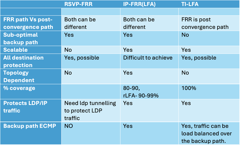
Segment routing TI-LFA combines the strengths of RSVP-TE FRR and IP FRR, discards the drawbacks, and introduces new features. Topology-independent LFA (TI-LFA) enhances the LFA and remote LFA concepts by enabling the Point of Local Repair (PLR) to utilize deeper label stacks to create backup paths.
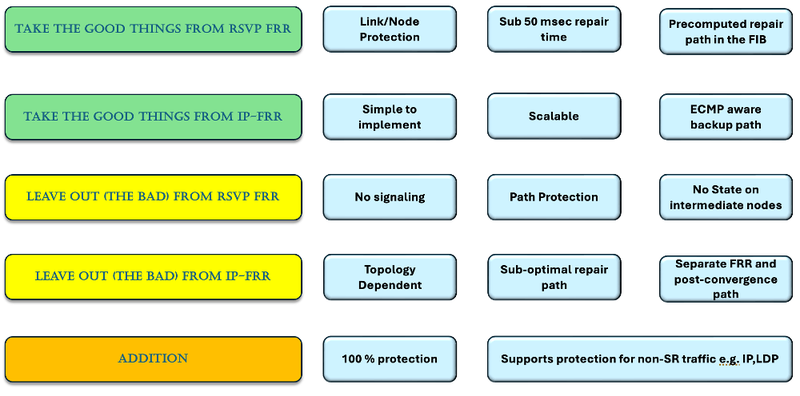
Figure 3 TI-LFA Integrates the best of IP-FRR and RSVP-FRR
Topology Independent Loop-Free Alternate (TI-LFA) is a version of LFA utilized in segment routing, which offers solutions to the challenges we encountered with RSVP-TE FRR and IP-FRR. It's as straightforward to set up as IP-FRR and provides us with complete 100% protection, similar to RSVP-TE FRR.
In RSVP-FRR and IP-FRR, the alternate or backup path often differed from the post-convergence path, frequently resulting in suboptimal routing. TI-LFA addresses this issue by delivering protection paths that align with the post-convergence path.
Unlike traditional LFA, which relies on the network topology to compute loop-free alternate paths, TI-LFA is designed to work with any network topology. This is achieved by using an algorithm that analyses the forwarding topology of the network rather than the physical topology.
Earlier, LFA (IP-FRR) was dependent on specific topologies and did not support all network scenarios. In contrast, TI-LFA is not restricted by topology, which is why it is referred to as Topology-Independent LFA.
TI-LFA is supported in routing protocols such as IS-IS (Intermediate System-to-Intermediate System) and OSPF (Open Shortest Path First) and can be configured on routers to provide additional redundancy and fast recovery in the event of link or node failures.
Benefits of using TI-LFA
Post-convergence path is the most suitable path for the repair path which avoids using the sub-optimal path and causing congestion on the link or in the network. In the case of failure, router pushes multiple labels (depend on P & Q node calculation) on packet and forward it over the repaired post convergence path.
As per the diagram below, the link between PE1 and P2 is protected as follows:
- The shortest path for traffic is via PE1 → P2 → P3 → PE4.
- The repair path for normal IP-FRR (LFA), based on RFC 5286, is evaluated as:
- Path 1: The condition
Distance (P7 → PE4)=40 < D(P7 → PE1)=10+D(PE1 → PE4)=30 is invalid.
- Path 2: The condition Distance(P6 → PE4)=100<D(P6 → PE1)=100+D(PE1 → PE4)=30 is valid, but it’s a suboptimal path.
- 2nd path via is chosen as a IP-FRR backup even though it’s a suboptimal routing ( low bandwidth)
- The post-convergence path is via P7-P3
- TI-LFA chooses the post-convergence path as the backup path via P7.
- The local router removes the protected link from the network graph and re-runs the SPF (Shortest Path First) algorithm to determine the post-convergence path (i.e., the second-best path). After completing this operation, the router identifies the P and Q nodes to determine the appropriate Segment IDs (SIDs) that need to be pushed onto the packet for TI-LFA operations.
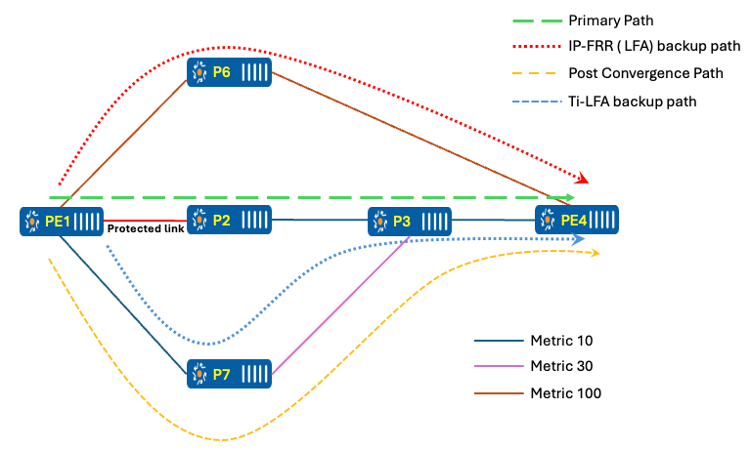
Figure 4 FRR and Post-convergence path Calculation
How does FRR works
A TI-LFA-enabled router runs SPF by removing the protected link from the topology graph to determine the post-convergence path. The router must identify the P, Q, or PQ node on this path to prevent traffic loops in the network. Once the appropriate node is determined, the router assigns the corresponding SID value: for a P node, it pushes the Prefix SID of the P node; for a Q node, it pushes the Adjacency SID between the P and Q nodes; and for a PQ node, it pushes the Prefix SID of the PQ node.
Routers determine the P, Q, and PQ nodes using the procedure outlined below.
- P Space/Nodes: Nodes reachable from the PLR (Point of Local Repair) without passing through the protected link or node.
By removing the protected link, the graph below illustrates the topology with PE-01 acting as the root. Similarly, for the destination, PE-04 is considered as the root in its respective graph. It's PLR (PE1) doing all PQ calculation for its selection of PQ node regarding a protected link/node
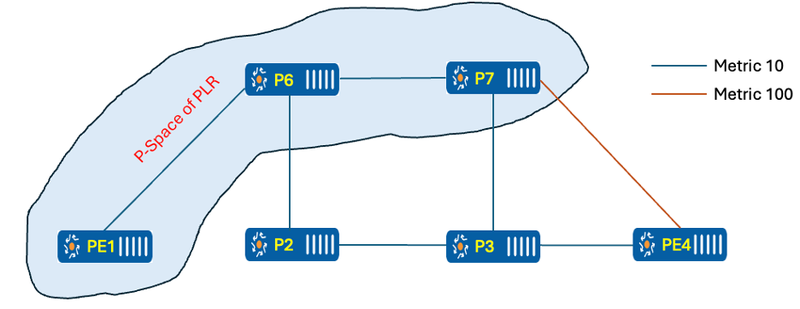
Figure 5 P Space of PLR
PE-01 can reach P-06 and P-07 without traversing the protected link. However, if PE-01 needs to reach P-02, P-03, or PE-04, it must go through the protected link. Therefore, only P-06 and P-07 is within the P-space of the PLR.
- Q Space/Nodes: The Q-space of a router with respect to a protected link is the set of routers from which that specific router can be reached without any path (including equal-cost path splits) transiting that protected link.
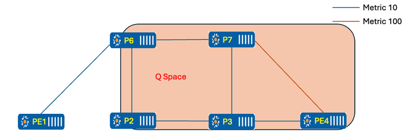
Figure 6 Q-Space
- PQ Nodes: Nodes that belong to both the P Space (or Extended P Space) and the Q Space are referred to as PQ Nodes.
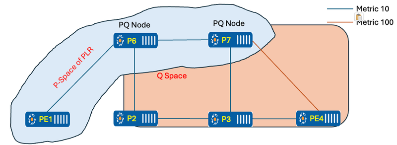
Figure 7 Calculation of PQ nodes
P-06 and P-07 are both acting as PQ nodes, but P-07 is chosen because it is closer to the destination, based on the selection rules. So, PE-01 picks P-07 as the PQ node and adds the P-07 Node_SID to the original packet when sending traffic over the TI-LFA path.
If multiple ECMP paths are available for TI-LFA, traffic can be load-balanced across them.
Data Path
VPN traffic destined for 192.168.2.2 carries an IPv6 header as the top header, with the destination r set to PE-04 locator-id (fcbb:bb00:) and the function (0:2::) representing uDT4. This indicates that the packet should be decapsulated and a version 4 routing table lookup performed for VRF-A.
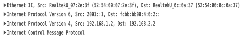
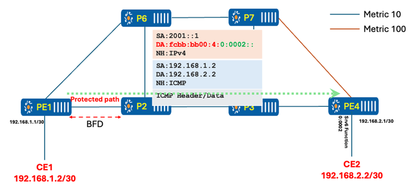
Figure 8 Shortest path between PE1 and PE4
Once the router detects a failure using BFD, the headend immediately switches the traffic temporarily over the protected or backup TI-LFA path. In this lab, P-07 acts as a PQ node, and the headend knows that if it sends the traffic to P-07 forcefully, it will not loop back, as P-07 forwards the traffic along the normal shortest path to reach PE-04. The headend will set the destination address of the IPv6 packet to P-07, and in the Segment Routing (SR) header, Segment (0) will represent the last hop, i.e., PE-04.
Once the packet reaches P-07, it copies Segment (0) from the SRH header into the IPv6 header as the destination address and forwards it towards the final destination.
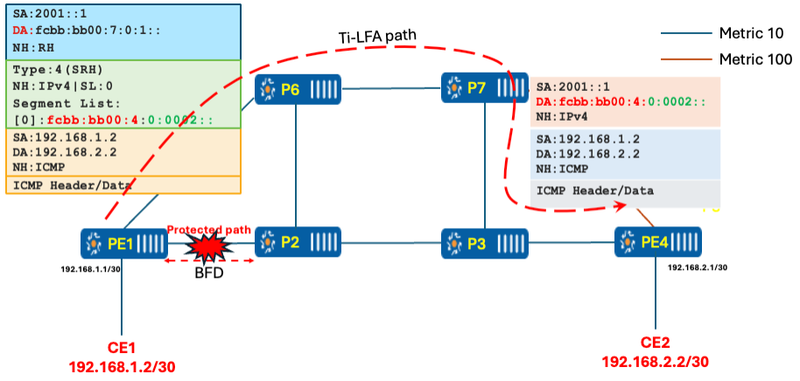
Figure 9 Traffic over TI-LFA backup path
Micro-loop in SRv6
Microloops are temporary routing loops that can occur in a network after a topology change, such as a link failure, restoration, or a change in routing metrics. These loops arise when nodes update their routing tables asynchronously, leading to situations where traffic is forwarded to a neighboring node that has not yet updated its routing information. This can result in traffic being looped between nodes, causing packet loss, jitter, and out-of-order delivery.
To address this issue, the Segment Routing Microloop Avoidance feature is implemented. This feature identifies potential microloops following a topology change. When certain topology changes are detected in IS-IS, the primary path of affected IS-IS routes forwards traffic over an SRv6 tunnel for a configurable delay. During this delay, a loop-free SR-TE (Segment Routing Traffic Engineering) policy path to the destination is established by leveraging a sequence of segments towards P/Q/PQ nodes. Once the RIB (Routing Information Base) update delay timer expires, the microloop avoidance path is replaced with the normal post-convergence next-hop, reverting to regular forwarding paths and ensuring network stability.
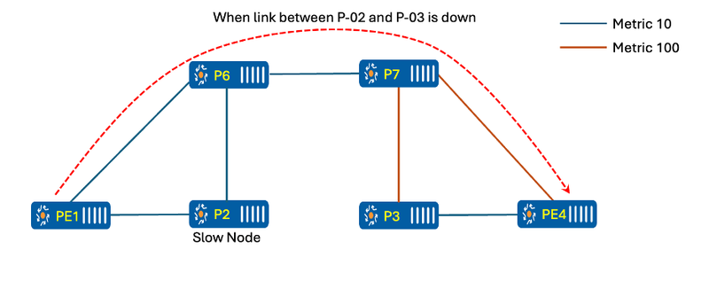
Figure 10 Traffic with link down between P-02 and P-03
When there are changes in the network (e.g., the link between P-02 and P-03 comes up), nodes PE-01, P-06, P-07, P-03, and PE-04 recalculate the SPF to determine the best path. While PE-01 and P-06 update their forwarding to point towards P-02, the challenge arises because P-02, being very slow in running SPF, is still pointing towards P-06. This results in packets looping between P-02 and P-06 as mentioned in below.
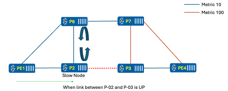
Figure 11 Link between P-02 and P-03 is up
Once P-02 completes its SPF calculation, it forwards packets along the correct shortest path. However, due to the node's slowness, microloops can occur in the network.
The router first detects a link up/down event or a metric change in the network, which could potentially cause a loop. To prevent this, the router pushes an additional segment on top of the packet using the MICRO_LOOP_AVOID_TUNNEL with extra SIDs and starts the RIB update delay timer.
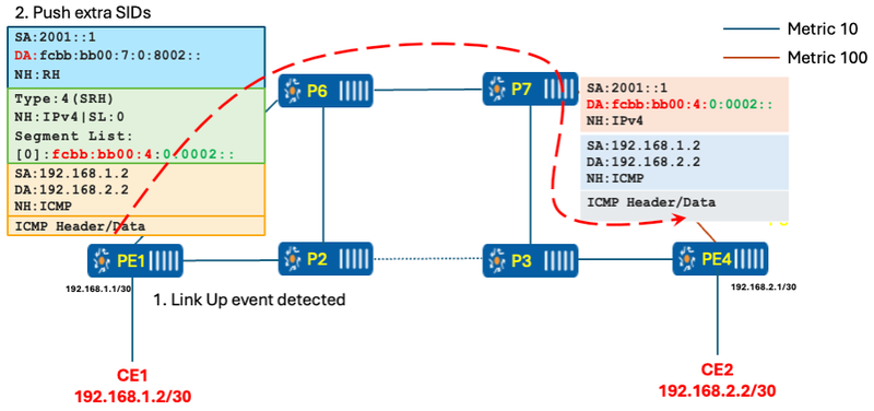
Figure 12 Link Up event detected
The router has already run the SPF calculation, but due to the RIB update delay timer, it is not immediately pushing the new updates to the RIB and FIB. Once the timer expires (e.g., 4.5 seconds in this case), the router updates the RIB and FIB with the new entries, allowing packets to flow over the newly calculated path as mentioned in below figure.
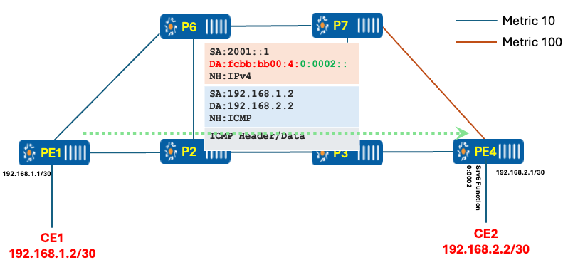
Figure 13 rib_delay_update timer expires
Conclusion
TI-LFA is a fast reroute mechanism designed to ensure minimal packet loss during network failures. It precomputes backup paths to protect against link or node failures, providing guaranteed repair coverage in segment routing-enabled networks. The key idea is to reroute traffic to a backup path (based on precomputed alternate paths) immediately upon failure detection, without waiting for the network to converge. TI-LFA uses Segment Routing to enforce these backup paths via explicit instructions (Segment IDs).
Microloops can occur during network convergence when routers update their forwarding tables at different times due to asynchronous updates. To mitigate this, microloop avoidance mechanisms, such as the use of RIB update delay timers, temporarily delay the installation of new routes into the RIB and FIB. During this delay, the router may use tunnels (e.g., MICRO_LOOP_AVOID_TUNNEL) with additional Segment IDs (SIDs) to forward traffic safely, avoiding loops. Once the delay timer expires, the updated paths are pushed into the RIB and FIB, ensuring a smooth transition to the new topology.